Our customers in the USA are managed by JW Winco. Please, use the website of JW Winco: jwwinco.com
Our customers in the USA are managed by JW Winco. Please, use the website of JW Winco: jwwinco.com


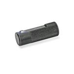
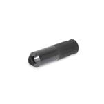
Spring loaded side thrust pins GN713 are versatile and practical elements for holding, positioning and clamping workpieces.
They eliminate costly alternatives, are space saving and simple to install. The protruding height of the thrust pin can be adjusted with the threaded body.
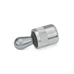
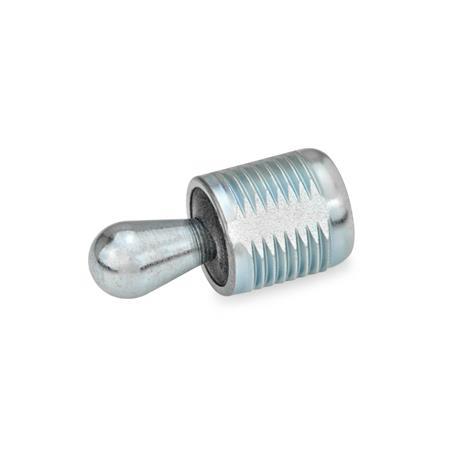
For mounting the side thrust pins a suitable mounting tool GN 713.1 is available (see table).
Housing Steel
Zinc plated, blue passivated
Thrust pin steel, hardened,
Zinc plated, blue passivated
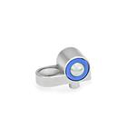
Pressure spring coding
Force
light: gray
medium: black
heavy: silver
Seal
Rubber NBR (Perbunan®)
RoHS

| SB | Thrust pin steel, with seal |
| SA* | Thrust pin steel, without seal |
| d1 | Side thrust force F0 in N ≈ at l2 | l1 -1,5 | d2 | a1 | a2 | ||||
|---|---|---|---|---|---|---|---|---|---|
| 5 | 20 | 50 | 100 | 11,5 | 19 | 26,5* | M 12 | 2,5 | 5,7 |
| 6 | 40 | 75 | 150 | 11,5 | 19 | 26,5* | M 12 | 3 | 7,7 |
| 10 | 100 | 200 | 300 | 18 | 31,5 | 45* | M 18 x 1,5 | 5 | 10,7 |
| d1 | k | l2 | l3 | s | w | x1 | x2 | Code No. for spanner |
|---|---|---|---|---|---|---|---|---|
| 5 | 1.5 x 45° | 6,7 | 6 | 10 | 1,6 | 1,7 | 1,3 | GN 713.1-5.6 |
| 6 | 1.5 x 45° | 10,7 | 10 | 10 | 1,8 | 1,9 | 1,4 | GN 713.1-5.6 |
| 10 | 2 x 45° | 16,7 | 16 | 16 | 3,2 | 3,4 | 2,7 | GN 713.1-10 |

|
w = Movement of pin For contact points (workpiece height) between a1 and a2 a value for x has to be used lying between x1 and x2 (interpolation). |
||||||||||

|
By observing the above values the full movement of the side thrust pin will be available to cover the tolerance of the workpiece. |
||||||||||

|
For inserting the side thrust pins the use of Mounting Tools GN 715.1 or Mounting Tools GN 713.1 is recommended. |
||||||||||
Our service team is available from Monday to Friday between 7:00 AM and 5:30 PM: +49 7723 6507 - 0